| Piezo Source - Technology Background | | Introduction | | | | Piezo tweeters, in use for 30 years now, offer a quality cost effective,
high frequency sound source in a rugged, high-efficiency package when used properly. Used improperly, however, they fail to
meet their potential. It is the purpose of this article to help the user attain the maximum benefits from pie-zohs, pizzas,
pee-zoids, or whatever else they have been called. | | | | Background | | | | Piezoelectricity was discovered by Jacque and Pierre Curie in the late 1880s. They
found that certain natural crystals generate an electric field under the influence of a mechanical force. They named the phenomenon
piezoelectricity, from the Greek meaning "pressure" electricity. The correct pronunciation is pi e' zo; however, Pe a' zo
(the Latin pronunciation) has become as common. Shortly thereafter, it was discovered that this phenomenon is a reversible one. That is,
when an electrical field is impressed across the crystal, it undergoes a physical deformation. Since the actual displacements are very small
(measured in millionths of an inch), the practical applications for piezoelectricity were slow in coming. The various natural occurring materials
were found to be piezoelectric, among them quartz, tourmaline, Rochelle salt, and even wood. The advent of radio resulted in the need for a
frequency-stable circuit component. quartz crystals, vibrating at resonance, were found to operate consistently and are still the state of
the art in frequency-stable components. This was the first high-volume major application of piezoelectricity. | | | | Underwater warfare in W.W.II generated a need for detection equipment analogous to radar used for
planes. It was known that acoustical signals travel extremely well in water, and the first acoustical application for piezoelectricity emerged. A
piezoelectric crystal was acoustically coupled to the water through a metal diaphragm. A short burst of energy (ping) caused the crystal to vibrate,
setting up and acoustical wave in the ocean. When the wave encountered a hard object, a reflected signal was returned to the sender. Since the
piezoelectric device also worked as a receiver, after the initial transmit "ping," it was switched to a receive mode and listened for the returning signal.
The time lapse between the transmit and receive was translated directly into distance. Further, by adding multiple receivers aimed in different directions,
a direction (bearing) could be determined. Rochelle salt was first used for this application because of its extremely high sensitivity. Unfortunately,
it exhibited several temperature and moisture problems that made its use impractical. | | | | A better material was needed. Independent research on both sides of the ocean resulted in a family of
synthetic materials that offer high electro-mechanical conversion efficiency with greatly improved temperature and humidity stability characteristics.
This synthetic material is actually a ceramic and is processed using methods similar to conventional ceramic sintering techniques. The material is called
PZT because it is a polycrystalline lattice structure of the oxides of Lead (P for Pb), Zirconium (Z), and Titanium (T). Since it can be formed using
conventional ceramic processes, it offers more design latitude to the transducer engineer than do crystals. | | | | A major difference between PZT and piezo materials found in nature (crystals) is that PZT must be processed
further to make it piezoelectric. The microscopic crystallites, known as domains, are in random orientation in the PZT and must be aligned if the material is
to be useful. This is done in a process called "poling." A high potential D.C. field is momentarily imposed across the material causing the domains to align
themselves with the field. Upon removal of the field, the domains remain aligned. The poled PZT is now truly piezoelectric and will stay that
way unless an excessively high voltage is imposed upon it, or unless it is heated to a very high temperature (Curie point). If either of these conditions is
reached, the energy input to the domains exceeds the internal binding force holding the domains in alignment, and the material once again becomes unpoled. This
entire process is very much like the magnetizing of a magnet except that we deal with electric fields instead of magnetic fields. It should be noted that the
ability of the PZT to retain its polarity is a function of the quality of the material. There are available low quality materials which will de-pole under normal
use causing the speaker to gradually lose efficiency (sensitivity). Piezo Source manufactures only the highest grades of PZT. | | | | Theory of Operation | | | | In operation, the domains within a poled PZT wafer (as shown in Figure 2) alter their position slightly when an
external field is applied. This causes a slight deformation in the physical geometry of the wafer. When the field is removed, the wafer returns to its original size.
These displacements are very small (measured in millionths of an inch) but high in force, and when coupled directly to a liquid or solid medium, are very useful for
generating discrete motions. When coupled to air, however, motions of these dimensions are useful only in the ultrasonic region where the acoustic impedance of the
air is higher, and provides a better match to the PZT. To provide useful motion in the audio region, a "mechanical lever", or transformer, is required to convert
the high-force, low-displacement motion to low-force, high-displacement. | | | | 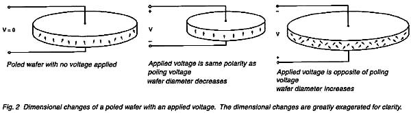 | | | | This is done by coupling two wafers face-to-face (see Figure 3). The wafers are connected such that as one expands, the other
contracts. When coupled at their faces with a metal member (centervane), the resulting stress causes the sandwich to dish in and out depending on the amplitude and polarity
of the applied signal. This "sandwich" is called a bimorph, as it consists of two active piezo elements. | | 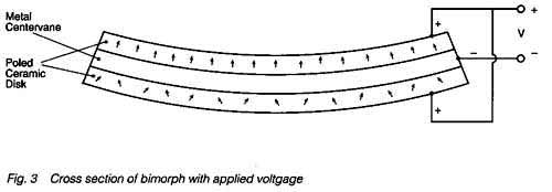 | | | | By affixing a cone to the center of the bimorph and anchoring the cone at its periphery, the bimorph
vibrates in synchronism with an applied audio signal and pumps the cone for and aft, while pushing against its own mass (Figure 4). This concept, called
the "Momentum Drive Principle" was developed and patented by Motorola in 1970. It is the fundamental principle behind a broad family of speakers introduced
in the ensuing 20 years through many technical developments and dozens of patents. | 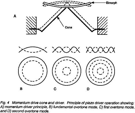 | | | | Piezo Tweeter Construction | | 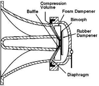 | | | | Let's consider, in detail, the construction of the Piezo Source Super Horn piezo tweeter. Although developed and
patented in the early 1970s, it is still a workhorse in commercial sound installations. The circular PZT bimorph in this case consists of two wafers, 0.89"
in diameter and 0.0055" thick. The ultra-thin wafer is required to achieve the desired acoustical performance. The bimorph is coupled at its center to the
apex of a specially impregnated diaphragm which then works into a compression volume. Slots in the compression the compression space direct the sound into
the throat of the horn. The radial slots are transformed into a 3" circular mouth through the unique shape in the throat of the horn. The actual horn
contour is a hybrid design between a pure exponential contour and a hyperbolic one. Again, this computer-generated geometry is optimized for the best acoustical output. | | | | 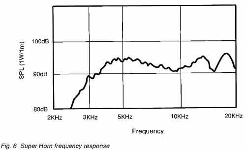 | | | | The result is a frequency response (Figure 6) showing high sensitivity and smooth characteristics. Again,
it should be noted that low quality products are available on the market using poorly tooled parts and imprecise manufacturing methods. The results are
inferior performance and unpredictable results. Piezo Source is proud of its commitment to quality and the consistently high performance of the full line at Piezo Source piezoelectric speakers. | | | | Piezo Tweeter Performance | | | | Because of the light dynamic mass of the piezo tweeter (no voice coil, spider, etc.),
the response is very fast. Tone burst measurements show the excellent transient response at all frequencies across the band. | | | | An additional advantage of the piezo tweeter is its high-power efficiency. With no voice coil, there is
no resistive heating and little lost acoustical power. In fact, the actual impedance of the tweeter (Figure 7) is very high, from about 50 ohms to
250 ohms for the Super Horn in its operating range. At these values, the amplifier sees the little additional load from the tweeter, allowing use of
arrays with little additional power load. Because it generates little waste energy it is capable of being driven harder than the dynamic tweeter. | | | | 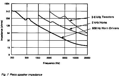 | | | | Application Hints | | | | With all the aforementioned virtues of piezo tweeters, there are still some issues in their use with
which the design engineer should be familiar. | | | | 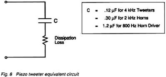 | | | | The piezo tweeter appears like a lossy capacitor to the amplifier (Figure 8). As shown in the impedance
plot (Figure 7) the impedance decreases with frequency. Many amplifiers today boast outputs that extend to 100 kHz. At those frequencies, ultrasonic
resonances may occur between the amplifier and the tweeter, causing damage to one or the other or both. | | | | If such an amplifier is used, particularly with an array of tweeters, a small series resistor is suggested
(Figure 9). For Piezo Source tweeters with a low-end cutoff of 3 kHz to 6 kHz, a 50 ohm, 2 watt resistor wired in series with each tweeter will prevent this resonance
problem without noticeably affecting the response. It should be noted that this problem is uncommon in automotive applications since these amplifiers usually
roll off at 20 kHz. The 2 kHz horn products do not require an external series resistor since one is built into each unit. The KSN1086 mid-range driver and
KSN1090 and 1103 voice range products should be protected with a 20 ohm, 10 watt series resistor. | | | |  | | | | Crossover Networks | | | | The piezo tweeter does not require a crossover network. Since the tweeter is capacitive in nature,
it rejects low-frequency power. However, if the mid-range is still operating at the turn-on of the tweeter (4 kHz in the case of the Super Horn), a harshness may
be heard in the total system. This disturbance in the crossover region
can be minimized by the addition of an R-C filter (Figure 10) tuned to attenuate the turn-on peak, rolling off the mid-range a little earlier.
If a conventional crossover network is to be used, the tweeter must be made to look "resistive" in order to work with the crossover. This can be done
by wiring an 8 ohm resistor across the piezo tweeter. It should be noted, however, that the power efficiency benefits are now lost since the
piezo tweeter will look more like an 8 ohm dynamic unit electrically. It will, however, allow the use of conventional crossover technology. If a variable level
attenuation is desired, an L-Pad can be used. | 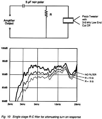 | | | | If a straight level attenuation is desired, a simple (non-polar) capacitor (Figure 11) can be series wired. | | | | 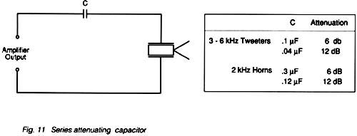 | | | | Multiple Tweeters | | | | System sensitivity can be increased by adding piezo tweeters in parallel (Figure 12). The high electrical impedance
of Piezo Source's piezo tweeters allows several units to be connected in parallel without overloading the amplifier. | | | | 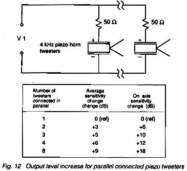 | | | | Each time the number of tweeters connected in parallel is doubled, the average sensitivity for the array
increases by 3 to 6 dB. The actual increase depends on factors such as off-axis angle, frequency, tweeter model and the configuration of the array. For
Piezo Source Super Horns, the on-axis response increases 6 dB for each doubling. Part of this increase occurs because of the narrower beam produced by multiple
horns. As the beam becomes narrower, the off-axis response degrades as a result of destructive interference between tweeters. The angle at which the
destructive interference is the greatest depends on the frequency and on the spacing between the tweeters. | | | | The destructive interference can be minimized in one plane by orienting a single row or column perpendicular to
that plane. For example, if horizontal dispersion is more important than vertical, the tweeters should be mounted in a single vertical column. This assures
that the horizontal dispersion of the array is identical to that of a single tweeter. The vertical dispersion, however, can begin to degrade significantly
beyond 5 degrees. Mounting the tweeters at an angle (off-axis) with respect to one another can also improve the off-axis response. | | | | 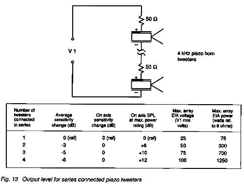 | | | | Connecting piezoelectric tweeters in series doesn't increase system sensitivity, but it does higher sound
pressure levels at maximum rated power (Figure 13). maximum power handling capability of the array increases as tweeters are added in series. At maximum
rated drive level, doubling the number of tweeters in series reduces the voltage across each tweeter by half with the resulting SPL decrease of 6 dB for
each tweeter. The additional tweeters, however, create a 6 dB increase for a net on-axis sensitivity change of 0 dB. If the voltage applied to the array is
now doubled, so that each tweeter sees it's maximum rated voltage, the array's on-axis SPL increases 6 dB. | | | |  | | | | 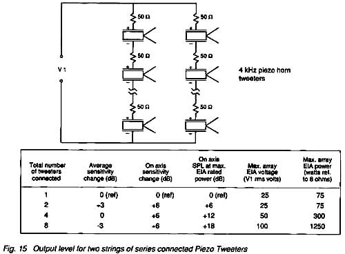 | | | | Power Handling | | | | The power rating of Piezo Source piezoelectric speakers is determined using the EIA RS426 test method. This is a
continuous 8 hour noise test with peak voltage spikes twice (4 times higher in terms of power) the average applied signal. Thus, for a speaker to be
rated at 75 watts (25 volts), it must not degrade after 8 hours of continuous operation at 75 watts with 300 watt spikes. As a result of using the EIA
test method, Piezo Source power ratings for its piezoelectric speakers tend to be conservative compared to conventional industry claims for speaker systems.
In addition, the extremely dense, high-quality ceramic manufactured by Piezo Source withstands cracking and other high power failure mechanisms much better
than the piezoelectric ceramic used by many other manufacturers. | | | | POWERLINE Series | | | | The POWERLINE series of 2 kHz horns use an internal protection circuit which allows the horn to continuously
handle the full output of a 400 watt (8 ohm reference) amplifier. The protector is a parallel combination of a miniature light bulb and a positive temperature coefficient resistor (PTC) (Figure 16). | | | | 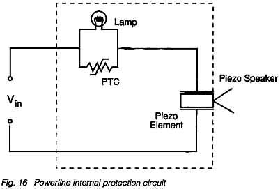 | | | | In a music system in which there is excessive clipping at high power, or high-amplitude high-frequency
signal content, the piezo drive element sees very large currents and will heat up due to dissipation losses. When the PTC senses the high temperature it
increases its resistance dramatically. This has the immediate effect of significantly lowering the power into the driver, and the SPL produced. To avoid
this sudden shift, and make the power control practically imperceptible, the miniature lamp is wired in parallel with the PTC. The lamp is essentially
a very fact-acting PTC and responds to music peaks rather than RMS heating as does the PTC. The audible effect is similar to that produced by a level
compressor. In this way, the driver is held below damaging levels. | | | | The resulting speaker performance then is as follows: under normal operating conditions, the POWERLINE speaker
performs in it's normal mode, faithfully reproducing the signal applied in proportion to its volume. Under temporary, extremely high power surges (even
in excess of 400 watts), the speaker will still perform in its normal expected mode. But now, if subjected to continuous high-frequency power, above 100
watts or so, the PTC temporarily opens up, allowing the speaker to continue to play, drawing its power through the light bulb, at a somewhat compressed
power level. The transition is smooth, and at the power levels being played at the time, barely perceptible to the human ear. When the speaker cools off,
the PTC automatically resets, and conditions return to normal. | | | | Conclusion | | | | The Piezo Source product line of piezo tweeters has grown dramatically since the Super Horn made its debut 18 years ago.
Piezo Source's speaker portfolio now includes mid-range drivers, voice range products, 2 kHz horns, and the Power Line family. Piezo Source is committed to total customer
satisfaction. With the wide variety of models available, and the technical tips provided herein, we are confident we can satisfy your audio design needs. |
|
|
|